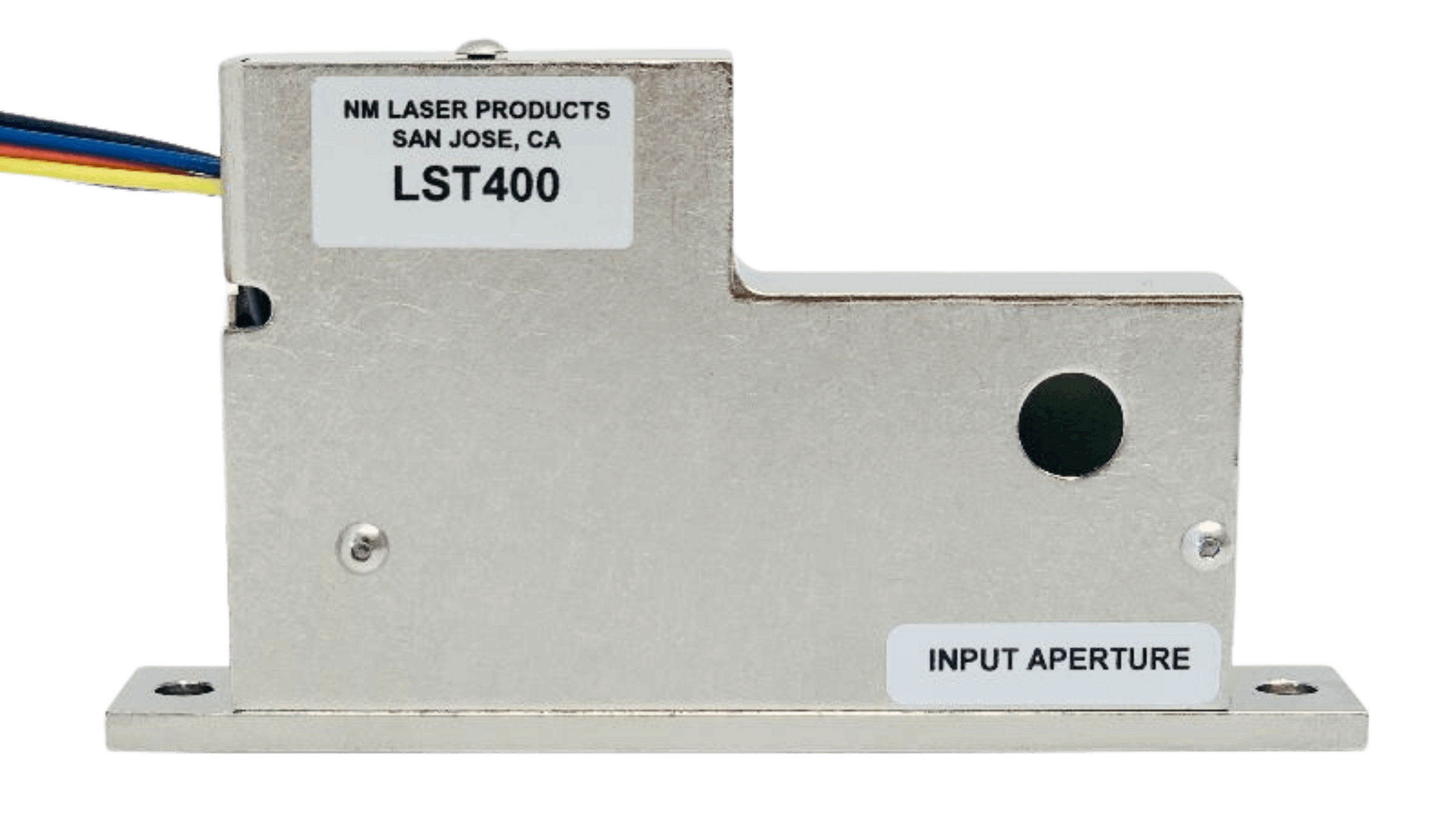
LST400-C2
$795
Features
Optical Power Handling: 50 W
Aperture: 8 x 12 mm
Switching Speed: 20 ms
Logic Position Sensors
Optics: Metal
LST400-AL
$695
Features
Optical Power Handling: 20 W
Aperture: 8 mm
Switching Speed: 20 ms
Logic Position Sensors
Optics: Metal
LST400-123
$795
Features
Optical Power Handling: 50 W
Aperture: 8 mm
Switching Speed: 20 ms
Logic Position Sensors
Optics: Dielectric
LST400-4
$795
Features
Optical Power Handling: 50 W
Aperture: 8 mm
Switching Speed: 20 ms
Logic Position Sensors
Optics: Dielectric
LST400
$695
Features
Optical Power Handling: 50 W
Aperture: 8 mm
Switching Speed: 20 ms
Logic Position Sensors
Optics: Metal or Dielectric
LST500-123
$1295
Features
Optical Power Handling: 100 W
Aperture: 15 mm
High Rep Rate: 15 Hz
High LIDT: 2 J/cm2
Optics: Dielectric
LST500-C2
$1195
Features
Optical Power Handling: 30 W
Aperture: 15 mm
High Rep Rate: 15 Hz
LIDT: 500 mJ/cm2
Optics: Metal
LST500-AL
$995
Features
Optical Power Handling: 20 W
Aperture: 15 mm
High Rep Rate: 10 Hz
High LIDT: 500 mJ/cm2
Optics: Metal
LST500-123-HP
$1295
Features
Optical Power Handling: 100 W
Aperture: 15 mm
High Rep Rate: 10-15 Hz
High LIDT: 2 J/cm2 @ 10 ns
Optics: Dielectric
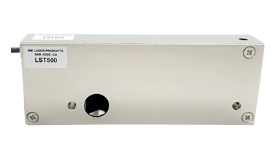
LST500
$995
Features
Optical Power Handling: 100 W
Aperture: 15 mm
High Rep Rate: 10 – 15 Hz
High LIDT: up to 2 J/cm2
Optics: Metal or Dielectric
LST800-C2
$1395
Features
Optical Power Handling: 300 W
Aperture: 16 mm
Switching Speed: 40 ms
LSTXYW8 Upgrade
Optics: Metal
LST800-AL
$1395
Features
Optical Power Handling: 20 W
Aperture: 16 mm
Switching Speed: 40 ms
LSTXYW8 Upgrade
Optics: Metal
LST800-20mm
$
Features
Optical Power Handling: 300 W
Aperture: 16 mm
Switching Speed: 40 ms
LSTXYW8 Upgrade
Optics: Metal & Dielectric
LST800-4
$1495
Features
Optical Power Handling: 300 W
Aperture: 16 mm
Switching Speed: 40 ms
LSTXYW8 Upgrade
Optics: Dielectric
LST800-3
$1495
Features
Optical Power Handling: 300 W
Aperture: 16 mm
Switching Speed: 40 ms
LSTXYW8 Upgrade
Optics: Dielectric
LST800-1,2,3,4
$1495
Features
Optical Power Handling: 300 W
Aperture: 16 mm
Switching Speed: 40 ms
LSTXYW8 Upgrade
Optics: Dielectric
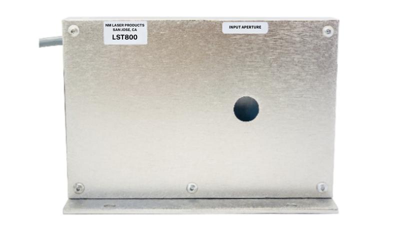
LST800
$1395
Features
Optical Power Handling: 300 W
Aperture: 16 mm
Switching Speed: 40 ms
LSTXYW8 Upgrade
Optics: Metal or Dielectric
LST4WBK2-3
$795
Features
Optical Power Handling: 50 W
Aperture: 4 mm
Switching Speed: 10 ms
Logic Position Sensors
Optics: Dielectric
LST4WBK2-AL
$695
Features
Optical Power Handling: 20 W
Aperture: 4 mm
Switching Speed: 10 ms
Logic Position Sensors
Optics: Metal
LST4WBK2-D123
$795
Features
Optical Power Handling: 50 W
Aperture: 4 mm
Switching Speed: 10 ms
Logic Position Sensors
Optics: Dielectric
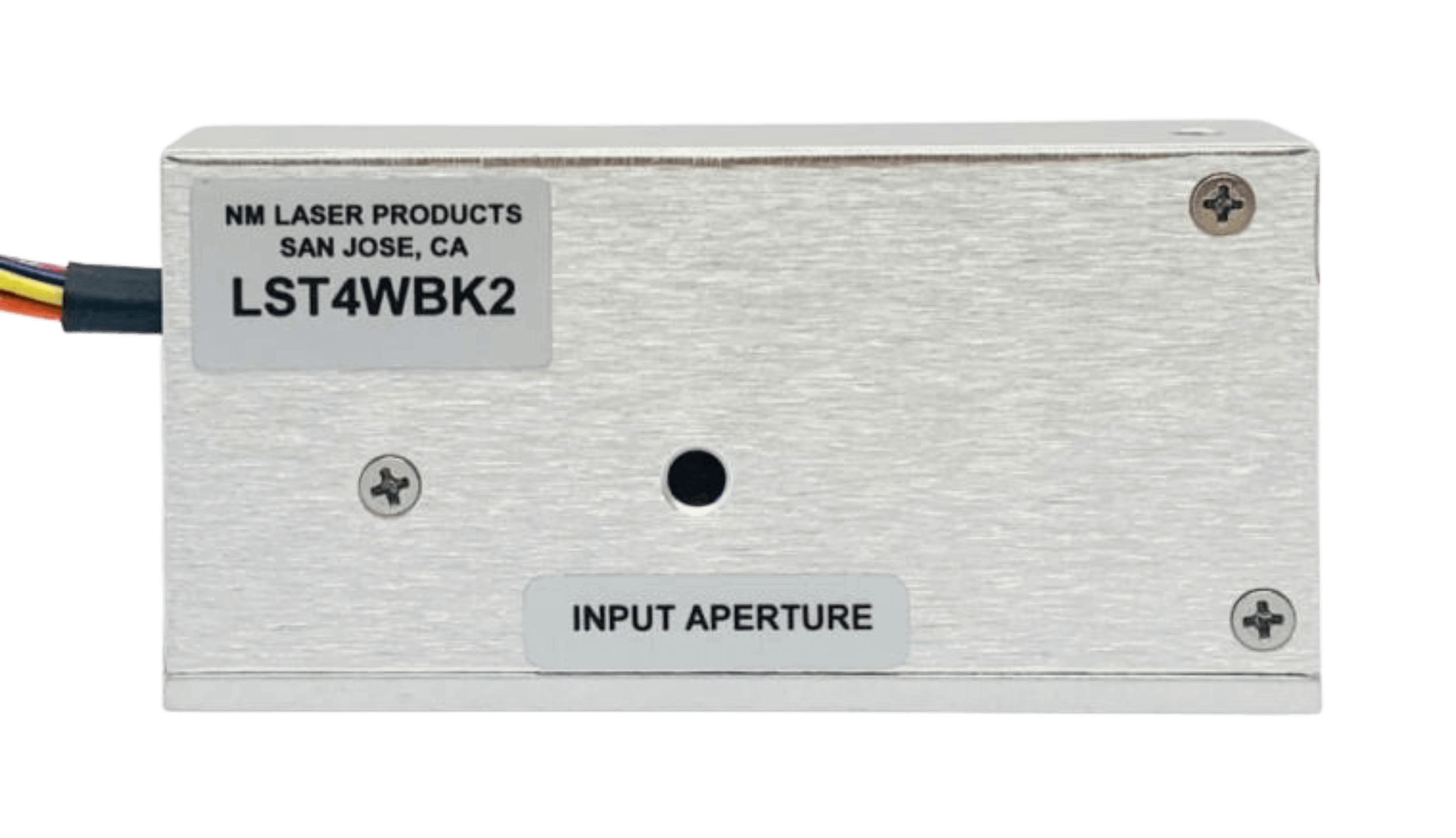
LST4WBK2
$695
Features
Optical Power Handling: 50 W
Aperture: 4 mm
Switching Speed: 10 ms
Logic Position Sensors
Optics: Metal or Dielectric
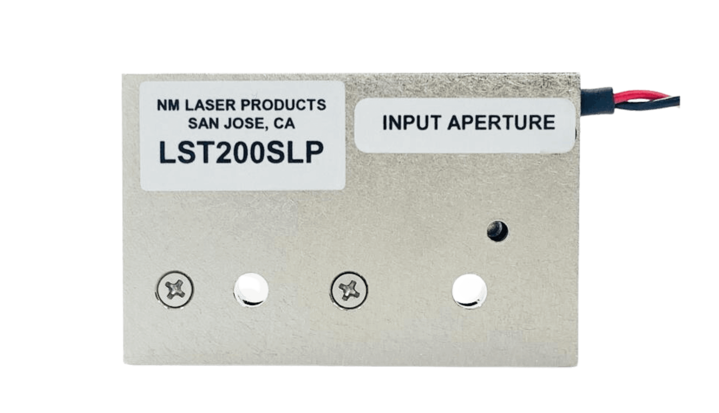
LST200SLP
$525
Features
Optical Power Handling: 2 W
Aperture: 2.3 or 3 mm Option
Switching Speed: 1 ms
Repetition Rate: 100 Hz
Lifetime: Billions of Cycles
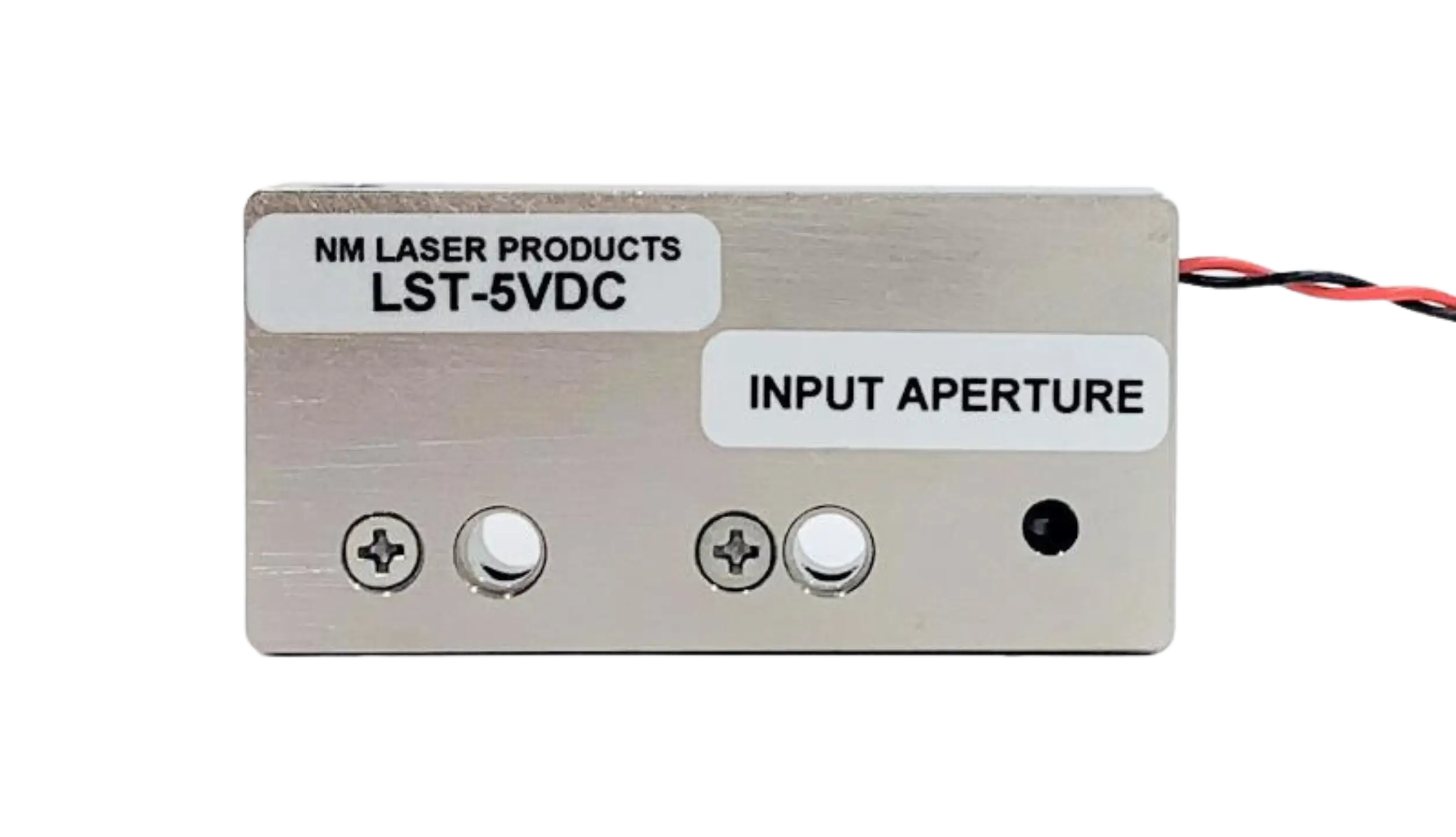
LST-5VDC
$395
Features
Optical Power Handling: 2 W
Aperture: 3 mm
Switching Speed: 2 ms
Direct Drive: 5V DC
No Controller PCB Needed
LST200-F40
$
Features
Optical Power Handling: 6 W
Aperture: 4 mm
Switching Speed: 8 ms
Position Sensors
Optics: Broadband
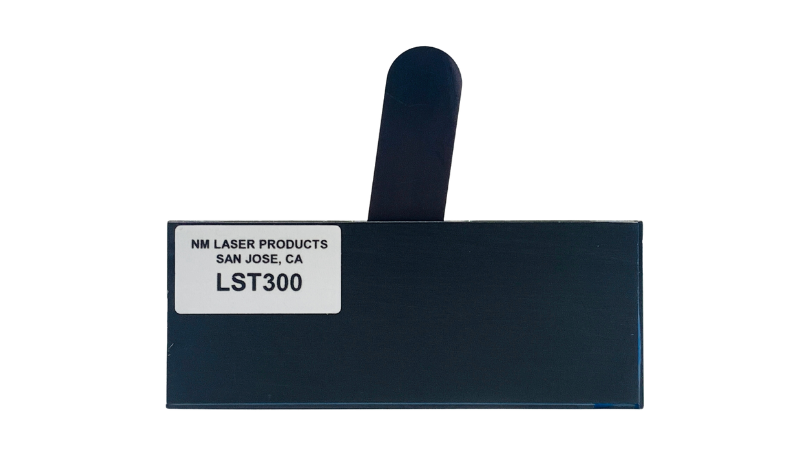
LST300
$695
Features
Optical Power Handling: 10 W
Aperture: 10.5 mm
Rep Rate: 5 Hz
LIDT: 500 mJ/cm2
Thin Optical Tongue Shutter
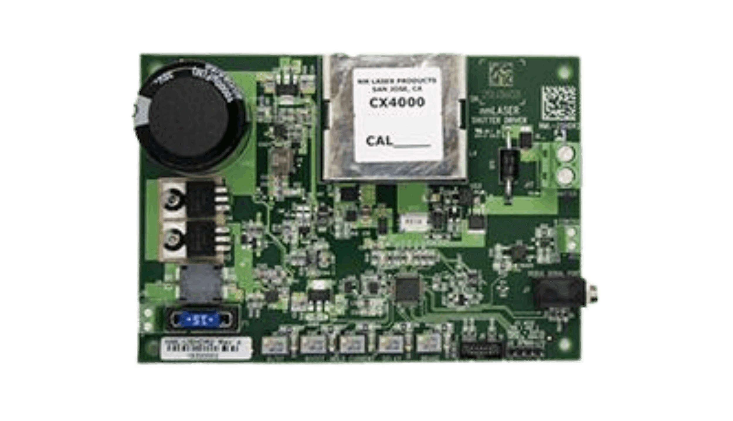
CX4000B
$
Features
Now Available with Enclosure Box
Fastest Switching Speeds
High Peak Currents
Analog/Digital Modes
Programmable Parameters