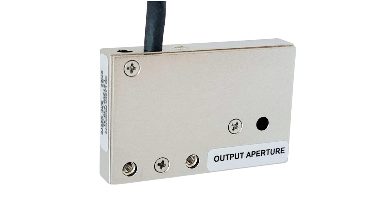
LST200-F40
Features
Optical Power Handling: 6 W
Aperture: 4 mm
Switching Speed: 8 ms
Position Sensors
Optics: Broadband
Contact us for pricing
Optical Power Handling: 6 W
Aperture: 4 mm
Switching Speed: 8 ms
Position Sensors
Optics: Broadband
Contact us for pricing
Applications
Optical Shutter
Biotech Exposures
500 Million Cycles
High-Reliability
Optical Shutter
Biotech Exposures
500 Million Cycles
High-Reliability
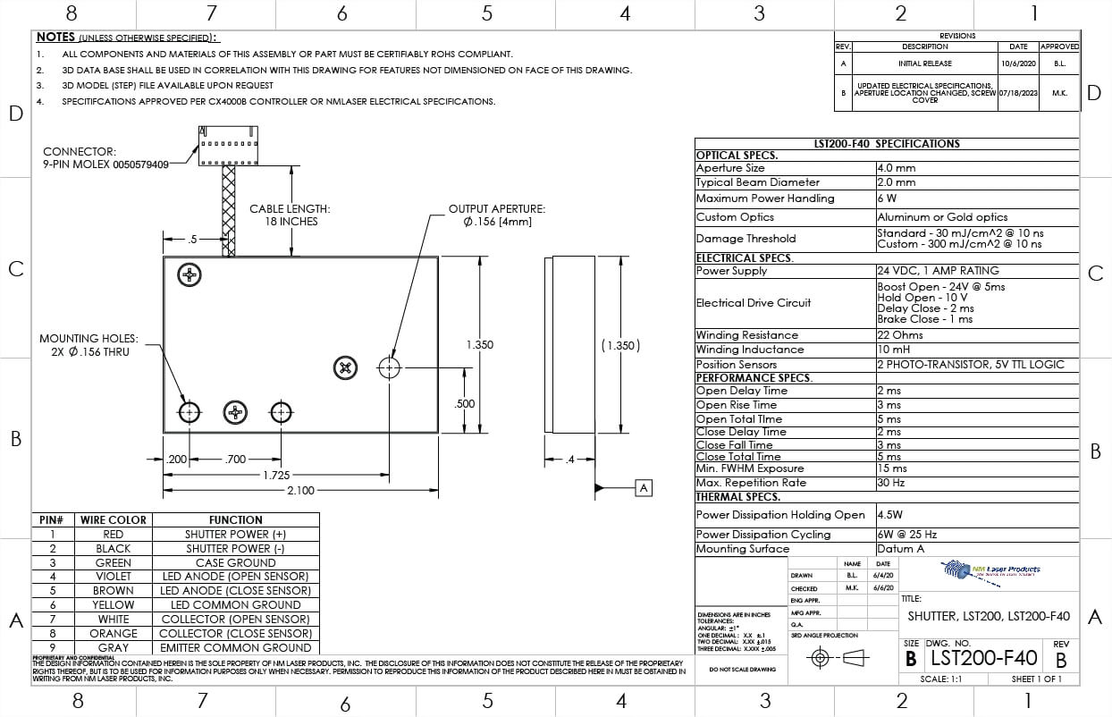
Optical Specifications
| Aperture Diameter | 4 mm |
| Typical Beam Diameter | 2 mm |
| Max. Optical Power Handling | 6 W |
| Optics Options | Aluminum or Gold |
| Typical Damage Threshold | Standard – 30 mJ/cm2 @ 10 ns Custom – 300 mJ/cm2 @ 10 ns |
Performance Specifications
| Open Delay Time | 2 ms |
| Open Rise Time | 3 ms |
| Open Total Time | 5 ms |
| Close Delay Time | 2 ms |
| Close Fall Time | 3 ms |
| Close Total Time | 5 ms |
| Min. FWHM Exposure | 15 ms |
| Max. Repetition Rate | 30 Hz |
Thermal Specifications
| Thermal Power Dissipation Holding Open | 4.5 W |
| Thermal Power Dissipation, Cycling | 6 W @ 25 Hz |
| Mounting Surface | Datum A |
Custom Options
| Optics Options | Aluminum or Gold |
| Wire Length | 2 ft. maximum |
| Connector | Any 9-pin connector |
| Identification | Engraving, Labels |
Electrical Drive
| Power Supply | 24 VDC, 1 A rating |
| Electrical Drive Circuit | Boost Open = 24V @ 5ms Hold Open = 10 V Delay Close = 2 ms Brake Close = 1 ms |
| Recommended Controller | CX4000B |
| Winding Resistance | 22 ohms Nominal |
| Winding Inductance | 10 mH |
| Position Sensors | 2 Phototransistors, 5 V TTL logic |
| Cable/Wire Type, No., Length, Termination |
26 AWG, 9 wires, 18 in., 9-pin Molex 0050579409 |
Wire Pin # - Color
| 1 – Red | Shutter Power (+) |
| 2 – Black | Shutter Power (-) |
| 3 – Green | Case Ground |
| 4 – Violet | LED Anode (Open Sensor) |
| 5 – Brown | LED Anode (Close Sensor) |
| 6 – Yellow | LED Common Ground |
| 4 – White | Collector (Open Sensor) |
| 5 – Orange | Collector (Close Sensor) |
| 6 – Gray | Emitter Common Ground |
Attributes
| Dimensions | 2.10 in. x 0.4 in. x 1.35 in. |
| Weight | ~6 oz. |
| Classification | Optical/Process |
| Gravity Considerations | None |
| Specifications Date | July 18, 2023 |