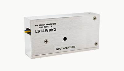
LST4WBK2 Laser Shutter
Features
Optical Power Handling: up to 50 W
Aperture: 4 mm
Switching Speed: 10 ms
Logic Position Sensors
Optics: Metal or Dielectric
Optical Power Handling: up to 50 W
Aperture: 4 mm
Switching Speed: 10 ms
Logic Position Sensors
Optics: Metal or Dielectric
$695.00
Applications
OEM Safety
High Rep Rate DPSS
Thin Working Zones
Small Package
OEM Safety
High Rep Rate DPSS
Thin Working Zones
Small Package
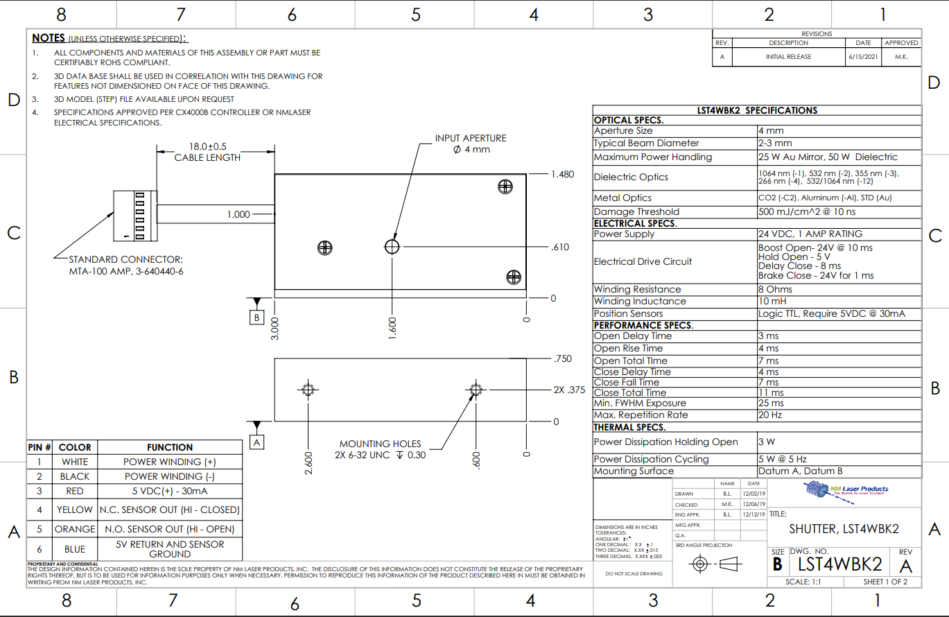
Optical Specifications
| Aperture Diameter | 4 mm |
| Typical Beam Diameter | 2 – 3 mm |
| Maximum Optical Power Handling | 50 W (Dielectric Optics) 25 W (Gold/Al Optics) |
| Optics Options | Gold, Aluminum, or Dielectric |
| Dielectric Optics Suffix | 1064 nm (-1), 532 nm (-2), 355 nm (-3), 266 nm (-4), 532/1064 nm (-12), 355/532/1064 nm (-123) |
| Metal Optics Suffix | CO2 (-C2), Aluminum (-AL), STD (Au) |
| Laser Induced Damage Threshold | 500 mJ/cm2 @ 10 ns |
Performance Specifications
| Open Delay Time | 3 ms |
| Open Rise Time | 4 ms |
| Open Total Time | 7 ms |
| Close Delay Time | 4 ms |
| Close Fall Time | 7 ms |
| Close Total Time | 11 ms |
| Min. FWHM Exposure | 25 ms |
| Max. Shutter Repetition Rate | 20 Hz |
| Lifetime | Available |
Thermal Specifications
| Thermal Power Dissipation Holding Open | 3 W |
| Thermal Power Dissipation, Cycling | 5 W @ 5 Hz |
| Mounting Surface for Thermal Sinking | Datum A, Datum B |
Custom Options
| Optics Options | Gold, Aluminum, or Dielectric |
| Wire Length | Any length |
| Wire/Cable Type, Wire Gauge | Teflon, Vinyl |
| Connector | Any 6-pin connector |
| Identification | Engraving, Labels |
Electrical Drive Data
| Power Supply | 24 VDC, +1.5 Amp Rating |
| Electrical Drive Circuit | Boost Open = 24 V @ 15 ms Hold Open = 5 V Delay Close = 8 ms Brake Close = 24 V for 1 ms |
| Recommended Controller (and Voltage Present) |
CX4000B (or Capacitor Discharge 24 V, 24 V PWM) |
| Winding Resistance | 8 ohms Nominal |
| Winding Inductance | 10 mH |
| Position Sensors | Logic TTL, Requires 5 VDC @ 30 mA |
| Cable/Wire Type, No., Length Termination |
22 g, six wires, 18 in., MTA-100, AMP, P/N 643813-60 |
| User Drive Circuit/Cap Discharge | 24 V, C = 2200 uF, R = 30 ohm, Flyback diode 1N4001 BUILT-IN STD |
| User Drive Circuit/PWM Type | 24 V for 15 ms, then drop to 5 V hold, use Flyback BUILT-IN |
| User Power Supply Notes | 24 VDC, 1 A Rating, Surge Capacitor on output, 3 A Rating |
Read sensor outputs with reference to the blue ground wire. These outputs are totem-pole buffered TTL, seeking a load of ~10 K ohms. Typical output is 4.5 V. Do not try to draw more than about 5 mA from the Yellow or Orange outputs, or the voltage will load down.
Wire Pin # - Color
| 1 – White | Power Winding (+) |
| 2 – Black | Power Winding (-) |
| 3 – Red | 5 VDC (+) – 30 mA |
| 4 – Yellow | Normally Closed Sensor Output (HI – Closed) |
| 5 – Orange | Normally Open Sensor Output (HI – Open) |
| 6 – Blue | 5V Return and Sensor Ground |
Attributes
| Dimensions | 3.0 in. x 0.75 in. x 1.48 in. |
| Weight | ~5 oz. |
| Classification | Safety/Process |
| Specifications Date | March 5, 2024 |